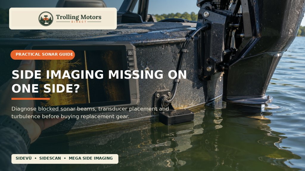
You idle past a brush pile, and the right side of your sonar screen looks like a detailed aerial photograph. The left side is a featureless dark wedge. You change the color palette. You turn up sensitivity. You wonder whether a new fish finder would fix it. But the problem may be a piece of boat hardware between the transducer and the water you are trying to see.
Side-looking sonar is unforgiving of blocked views. Garmin calls its scanning technology SideVü, Lowrance uses SideScan, and Humminbird calls its version Side Imaging.
They differ in processing, frequency options and interface, but all depend on a suitable transducer sending sound to both sides of the boat and receiving the echoes. A perfectly good display cannot reconstruct returns from a beam that strikes your outboard, hull, jack plate or an unsuitable mounting surface first.
This guide is a diagnostic workflow—not a demand to drill another hole. Start with the picture, document your configuration, perform safe dockside checks, then make one controlled change at a time.
You will learn what an obstruction looks like, how speed and disturbed water change the image, which settings matter, and when a second transducer or professional installer might be justified.
If you’re experiencing side imaging missing on one side, the troubleshooting steps below will help you identify possible causes before investing in replacement equipment.
First, understand what the image should show
A typical side-imaging view splits the display at the boat’s track. The near-center darker band represents the water column beneath and beside the vessel; bottom returns grow outward toward greater side ranges. Bright surfaces can mean stronger acoustic returns. Shadows behind a stump, rock or drop are often at least as informative as bright highlights. The interpretation depends on range, frequency, palette, depth and boat speed.
Garmin describes SideVü as a way to see structure and fish off both sides of a vessel. A screen with strong detail on one side and a persistent blank area on the other is not automatically proof of a damaged transducer. It means you should separate three questions: Can that beam physically leave the transducer? Is the transducer in clean water? Is the display set to show the expected sonar source and view?
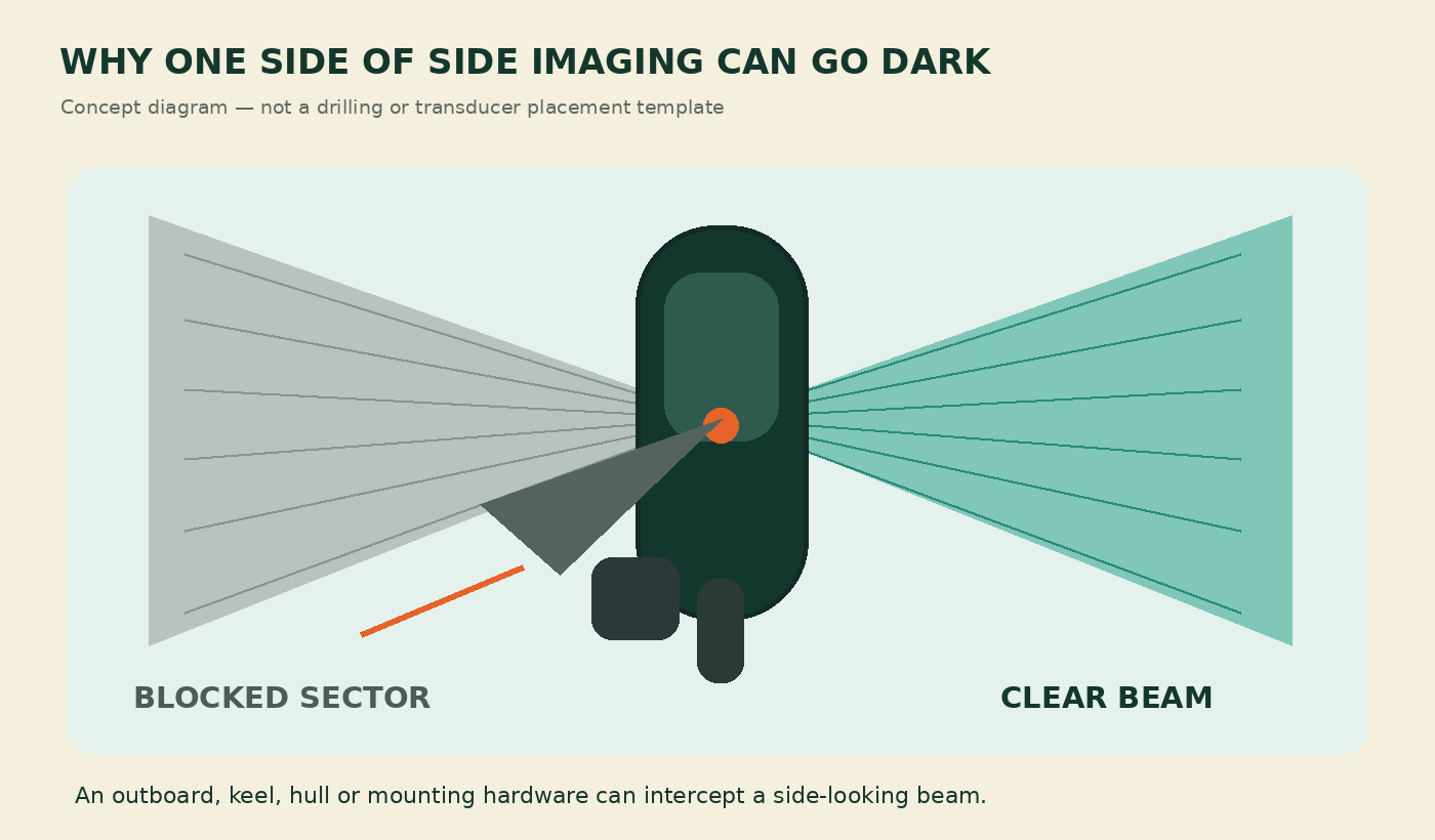
The original diagram below illustrates a possible mounting obstruction. It is a conceptual drawing, not an installation template or a manufacturer-approved mounting position.
Side Imaging Missing on One Side? Recognize the Symptoms Before Adjusting the Mount
| On-screen symptom | Plausible explanation | Best first check |
|---|---|---|
| One side remains dark in the same way every pass | Outboard, hull, bracket or keel obstructs that beam | Observe transducer line of sight and motor trim while stationary |
| Both sides fade as boat speed increases | Turbulence, aeration or transducer losing clean water | Repeat at slow constant speed; examine hull features upstream |
| Picture breaks into repeating bands when equipment turns on | Electrical or acoustic interference | Compare with other equipment off, then on one item at a time |
| The return is confusing but both sides still show bottom | Range, contrast, sensitivity, palette or interpretation | Restore a known-good view and adjust a single setting |
| A previously working image becomes intermittent after transport or impact | Connector, cable, loose bracket, damaged transducer | Inspect de-energized cabling and mounting hardware |
| Only a trolling-motor-mounted view changes when steering | Transducer rotates with the shaft; boat can obstruct its view | Compare beam orientation in several safe steering positions |
The table is a triage aid, not a remote diagnosis. Two causes can produce similar screens, and more than one problem may be present.
Step 1: Document a repeatable, safe on-water test
Before moving hardware, save the current settings or photograph each relevant sonar page. Note which transducer is selected, where it is mounted, your depth, water conditions and whether the outboard is trimmed up or down. If a networked system offers several sonar sources, identify the one feeding the screen; changing settings for the wrong input will waste a morning.
Choose sheltered water without traffic or obstacles. Have another adult handle the helm if observation demands it. Keep hands away from propellers, use the engine manufacturer’s safe tilt and trim procedure, and never reach below a moving boat. When studying an obstruction, make the geometry observation with propulsion off and the boat secure; then retest the image from a proper operating position.
The three-pass comparison
- Baseline: Make a short, straight pass at a steady slow speed. Record the left and right images and the range setting.
- Repeat: Run the same line in the reverse direction at a comparable speed, keeping the sonar range fixed. Different bottom composition can fool you, so the same path provides a useful control.
- Change one variable: After securing the boat, inspect an obstruction or adjust one permitted setting; make another pass and compare screenshots.
A missing return that remains on the same display side as the boat reverses is more suspicious for rigging or beam geometry than a return that moves with the underwater feature. This is an inference, not a universal test result. Currents, bottom slope and boat orientation still matter.
Step 2: Check for a physical obstruction before adjusting sensitivity
If you notice side imaging missing on one side, first check whether the transducer has an unobstructed sightline in both directions. Humminbird explicitly explains that an outboard motor or other boat feature may block a side-imaging beam. Its support documentation explains that an outboard can block one beam and that, on appropriately supported systems, a second matched transducer and a model-specific Y-cable can resolve some installations. That is a manufacturer-specific option, not permission to mix arbitrary transducers and splitters.
Inspect the hull from behind at the waterline and picture a beam extending sideways from each side of the transducer. The outboard lower unit may obstruct the inboard side of a transom-mounted sensor. A stepped hull, a deep keel or a transducer mounted too far toward a chine can also limit what one side sees. Jack plates, trim tabs, ladders and other accessories deserve a look.
Why simply moving the sensor lower can be wrong
Lowering a transducer may improve clearance past a nearby structure, but it can also expose it to debris, increase drag, worsen spray or place it at risk during trailering. Raising it may protect the sensor yet move it into aerated water. There is no universally correct inch measurement: follow the installation drawing for the exact transducer, hull type and mounting method, not the dimensions of another angler’s boat.
On a V-hull, installing a side-imaging sensor against a steep hull surface can send part of the beam into the keel. Garmin’s placement guidance discusses configurations where a single transducer cannot see both sides of a deadrise hull and where paired transducers may be appropriate. That guidance is about a particular installation style; not every Garmin display supports every paired-sensor arrangement.
Does trimming the outboard change the picture?
If the outboard occupies the inboard beam’s path, a small permitted change in motor trim while the boat is secure can reveal the obstruction in a controlled observation. But do not treat running with an unsafe trim position as a permanent solution. The durable answer may be a better mounting location, a compatible paired setup or an installer who can design around the hull.
Step 3: Separate blocked beams from turbulent water
A transducer does its best work in solid, relatively undisturbed water. Strakes, rivets, steps, through-hull fittings and propeller wash can create bubbles. The bubbles scatter acoustic energy and may cause partial or complete loss of returns. Garmin’s mounting advice recommends avoiding fittings or hull features that create turbulence. Humminbird’s installation material similarly emphasizes a location with relatively clean flow and warns that rough water and air bubbles can interfere with side imaging.
Ask when the symptom appears. If detail is excellent at idle but vanishes when the hull starts to plane, you may have a water-flow problem rather than a dead imaging channel. If the dark wedge persists at every speed on just one side, inspect obstruction geometry first. These are practical signals, not infallible rules.
A practical water-flow inspection
At the dock, look forward along the hull from the proposed transducer position. Is there a strake or rivet row feeding a trail of bubbles into it? Is the sensor directly behind a step that changes the water contact point as the boat accelerates? Does a trailer bunk touch the bracket during loading? Check for weed, algae or dried deposits on the face using only cleaning methods approved by the manufacturer.
Do not perform a high-speed visual inspection from the transom. Have a qualified installer evaluate flow or use a safe, approved camera arrangement if a dynamic check is necessary. A location that works for 2D depth at higher speed is not automatically the best place for a wide side-looking image.
Step 4: Confirm the exact sonar mode, source and orientation
The labels SideVü, SideScan and MEGA Side Imaging are not interchangeable product features. A chartplotter may be capable of displaying a side-imaging screen while the installed transducer lacks that capability. Garmin’s own documentation notes that some devices require a compatible sonar module as well as a compatible SideVü transducer. If the display does not offer a side view, verify the hardware first.
On a boat with a console screen, bow screen, trolling-motor transducer and transom transducer, the wrong source is a common diagnostic trap. Write down the actual transducer model, connection path and selected source shown in the unit’s menus. Consult its current manual for orientation options or transducer-type selection; never guess which setting belongs to a particular model.
Adjust the display in a controlled order
Begin with a short, manageable side range that includes a piece of known structure on both sides. Select the correct side-imaging view, then compare the manufacturer’s automatic contrast or gain option with a manual change if available. Change palette only to help interpretation; color cannot remove a blocked beam. Keep the same boat speed and sonar frequency during your comparison so two variables do not change at once.
Humminbird’s troubleshooting guide recommends checking operating mode, restoring suitable settings when needed, testing accessories and cable connections, and verifying that a selected transducer is capable of side imaging. If you restore defaults, document waypoints, saved views and network settings first because reset scope varies by device.
Step 5: Distinguish signal interference from geometry
An electrical issue can make a side-imaging display look noisy, but noise is not the same as an opaque blocked wedge. Repeating bars, broad speckling or rhythmic changes tied to the trolling motor, charger or other electronics suggest a different investigation. Sonar frequencies can also interact when multiple sounders are operating nearby.
For a safe isolation test, take screenshots with ancillary electronics off, then re-enable devices individually. Do not unplug transducers or open electrical circuits while energized. Check battery supply voltage only using the prescribed service procedure, and ask a qualified marine electrician to investigate questionable grounds, fuses or wiring. This article does not substitute for a wiring or interference installation manual.
| Comparison | Obstruction hypothesis | Interference hypothesis |
|---|---|---|
| Visual pattern | Fixed sector or persistent one-sided loss | Moving bands, noise, sometimes across both sides |
| Correlates with | Physical hardware and steering/trim angle | Other electronics switching on or changing load |
| First controlled action | Inspect line of sight | Isolate equipment and compare screenshots |
| Potential remedy | Correct mount placement or supported paired sensors | Manufacturer-guided wiring, power or sonar settings |
Keep a photographic record. It helps a support technician make a recommendation without relying on an ambiguous description like “the left side looks weird.”
Step 6: Know when a second transducer actually makes sense
A second transducer is not a universal repair. Humminbird identifies certain side-imaging paired arrangements using matched sensors and specific left/right Y-cables. The right cable family varies by control-head series. For another manufacturer or another generation, the architecture may be entirely different.
Before purchasing any extra hardware, confirm the part number printed on your transducer, the exact chartplotter model, whether the manufacturer supports a paired installation, whether the cable is a left/right imaging splitter rather than a general-purpose power or network splitter, and whether your hull has space for a proper second location. The expense of a second component is harder to justify if a simple mount adjustment can restore the view.
Where product selection intersects with the diagnosis
If you are beginning from zero, Garmin ECHOMAP UHD2 93sv with GT56UHD-TM is a store-listed package that includes a SideVü-capable transducer. The Lowrance HDS12 PRO with Active Imaging HD 3-in-1 includes SideScan-capable hardware, while the Humminbird XPLORE 9 CMSI+ includes its MEGA Side Imaging+ transom transducer. These are three separate ecosystems; none of these transducers is being presented as universally compatible.
If you already own a display, buying a new bundle can be unnecessary. Use the model number, source selection and mounting problem to narrow the parts list. Browse the store’s fish finders and chartplotters only after you know what you need to replace or add.
Three real-world diagnostic scenarios
Scenario A: One bright side, one black sector on a bass boat
An angler’s console display shows crisp right-side trees but almost nothing left of center. The sensor sits near the starboard side of the transom; the outboard lower unit appears directly between the left beam and open water. The angler documents the baseline, secures the boat, inspects the sightline, and asks the installer whether a manufacturer-approved relocation or paired arrangement is appropriate. Replacing the display first would be a poor sequence because a new screen cannot remove the lower unit.
Scenario B: Both sides work at idle, then become speckled
A multispecies boat shows good detail at a slow, even trolling speed, but loses clarity as it accelerates. The owner checks the location relative to a hull strake and a nearby water pickup, then has the mounting position reviewed for turbulence and height. Boosting contrast may brighten the noise; it does not restore clean water across the transducer face.
Scenario C: The bow screen changes when the trolling motor turns
A side-looking transducer mounted on a trolling motor rotates when the shaft steers. In one heading it views open water; in another the boat’s hull becomes a nearby obstruction. The owner compares steering positions safely, confirms that the correct source is selected and decides whether boat-relative sides, rather than transducer-relative sides, are necessary for the way they fish. A fixed transom sensor and a steerable bow sensor serve different jobs; the best location depends on the fishing method.
A pre-purchase and pre-installation checklist
- Photograph the failing image with depth, range, mode and boat speed visible.
- Record the display model, software version and transducer part number.
- Identify where the chosen source is physically mounted.
- Check port and starboard lines of sight to avoid the hull or outboard.
- Check for strakes, steps, propeller wash and trailer-bunk interference.
- Inspect the transducer face, bracket, cable and plug with power off.
- Compare one steady-speed baseline with the same path in reverse.
- Change only one supported setting or mounting variable per test.
- Confirm any proposed dual-transducer solution in the exact manufacturer manual.
- Document what improved, what did not and what still needs professional evaluation.
Frequently asked questions
Why is one half of my SideScan screen black?
A nearby hull feature, lower unit or bracket may be blocking a beam, but source selection, a damaged cable and system settings are also possibilities. Start with a controlled comparison and a physical obstruction inspection rather than ordering a replacement transducer immediately.
Can a bad transducer still show one side?
Potentially. A partial failure or cable issue can produce uneven behavior, but a one-sided image alone cannot distinguish electronic failure from a blocked acoustic path. Follow the manufacturer’s component test or ask qualified support to isolate the cause.
Should I turn up sensitivity to fix a black side?
Sensitivity can change the display of echoes that actually return. It cannot turn an obstructed beam into an unobstructed one. Record the default and adjust only after checking the selected source and sensor geometry.
Does Side Imaging work when the boat is stopped?
The unit may display returns while stationary, but side-imaging history builds more usefully as the boat moves steadily. A stationary display can repeat the same narrow view rather than drawing a map of new bottom. Use the maker’s operating recommendations for your model and conditions.
Will trimming up the outboard always solve the problem?
No. It may reveal a motor obstruction, but a keel, transom step, nearby transducer or turbulence can cause similar symptoms. Trim only within safe operating limits and choose a permanent installation based on the relevant manual.
Can I use one left-side and one right-side transducer?
Some Humminbird systems explicitly support paired transducers with specific splitter cables. Other arrangements differ. You need exact compatibility by display, transducer and cable; do not treat ordinary Y-cables as interchangeable.
Is a bow-mounted scanning transducer better than a transom-mounted one?
Neither is automatically better. A transom sensor is useful while surveying structure from the helm; a bow-mounted one shows the water you are fishing near the trolling motor but rotates as you steer. Many anglers use different sensors for different tasks.
When should I stop troubleshooting and call a professional?
Stop if installation requires inaccessible hull drilling, modification of critical wiring, questionable cable repairs, work near moving propulsion, or changing an unfamiliar thru-hull installation. Bring the technician screenshots, part numbers and a description of the controlled tests.
Get the image right before buying more electronics
Side imaging missing on one side can indicate a blocked sonar beam, disturbed water flow, or an equipment configuration issue. The cleanest side-imaging picture starts with an unobstructed beam, suitable water flow and a properly configured compatible system—not a brighter color palette. Work through those basics, identify your exact transducer, and decide whether you need a placement correction, a manufacturer-approved second sensor or a genuinely different unit.
Before ordering, compare Trolling Motors Direct’s fish finder selection and email sales@trollingmotorsdirect.org with your boat model, current display, transducer number and two screenshots. That is enough information to have a much more useful compatibility conversation.