The fish finder is bright and steady at the dock. You deploy the trolling motor, touch the speed pedal, and the display goes black. A logo appears. Your map takes another minute to load, and the screen is fine—until the next hard steering correction. It feels like a defective chartplotter, but the failure may be happening somewhere between the battery and its power connector.
A fish finder that repeatedly restarts while the trolling motor operates may be experiencing voltage drop, an overloaded power circuit, a loose connection, or a device-specific fault. Identifying the exact symptom is essential before replacing the display.
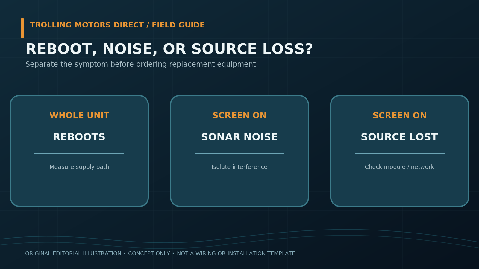
If your fish finder restarts when the trolling motor runs, the next step is to separate power loss from other symptoms. A graph that reboots is not necessarily suffering the same problem as a graph that stays on but shows sonar noise. A reboot can indicate momentary loss of operating voltage, a loose connection, or a device/software fault. Horizontal lines or static on a continuously powered sonar screen point to a different diagnostic path. The distinction matters because an expensive new graph will not fix a corroded fuse holder or a shared, overloaded feed.
This is a methodical, non-invasive investigation for boat owners using Garmin, Lowrance, or Humminbird electronics alongside an electric trolling motor. It includes a load-paired voltage comparison, a fault-isolation matrix, and an upgrade decision checklist. It is not a wiring diagram, substitute for the model-specific installation manual, or authorization to work on energized marine circuits.
First separate a reboot from a sonar picture problem
Ask a precise question: Does the entire display actually lose power? If the manufacturer’s boot logo returns, chart pages reload, and the unit reconnects to the network, you likely observed a restart. If the interface, time, and map remain uninterrupted while the sonar image shows stripes or speckling, you saw picture interference. If only the transducer or networked sonar source vanishes while the display stays on, diagnose that accessory’s power and data connection separately.
A three-way symptom check
| Observable symptom | Likely investigation path | Evidence to capture |
|---|---|---|
| Whole display goes black and shows startup logo | Supply voltage, connector, fuse/ground path, internal reboot | Short video; timing relative to trolling-motor load |
| Display stays on, sonar develops bands or snow | Electrical/acoustic interference, transducer routing or sonar settings | Screenshot at equal range before and during load |
| Chart and menu stay on, external sonar module disconnects | Module supply, networking, accessory connection | Exact alarm or “source lost” message |
| Display powers down when engine cranks | Starting-battery voltage sag or distribution issue | Voltage behavior during engine start, model-specific power spec |
| Display resets when a pedal or mount is moved | Intermittent connector or damaged cable near movement | Movement/action that reproduces the fault; no live probing |
The table identifies where to look first. Several faults can coexist; the most visible symptom is not proof of one cause.
Why a fish finder can reboot on a “healthy” battery
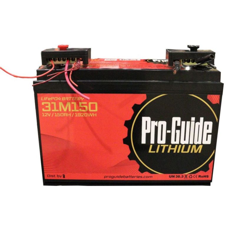
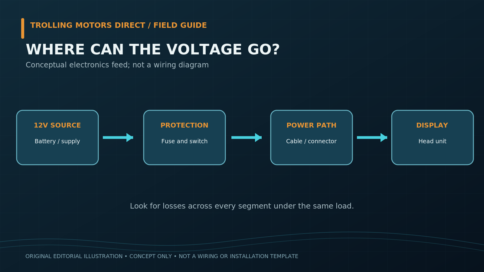
Batteries are not perfect fixed-voltage supplies. When a motor draws current, the source voltage may dip. Any resistance in a long cable, damaged crimp, oxidized terminal, switch, fuse holder, or undersized extension adds more loss. The graph receives what remains at its own power connection, not what an unloaded voltmeter once read at the battery.
For simple DC systems the relationship is: voltage drop = current × resistance. This is a diagnostic explanation, not a specification for wire sizing. If the wire run is twice as long, the conductor resistance is generally higher, and both the outgoing positive and return paths count. The size and allowable drop depend on the device, cable length, installation details, and manufacturer requirements.
A battery can therefore show acceptable resting voltage and still fail to supply a stable chartplotter during a demanding load. Humminbird explicitly includes weak batteries, connectors, charging issues, and power-cable voltage drops in its fish finder power troubleshooting guidance, updated November 9, 2026. That same guidance recommends testing the system under load, not just with everything switched off.
A crucial distinction: 12V graph versus 24V/36V motor
The trolling motor’s battery bank may be 24V or 36V. That does not mean a conventional 12V fish finder can be connected directly across the full trolling-motor supply. Use the display’s specified input range and approved power design. Do not tap one battery within a multi-battery series bank without manufacturer-approved system design; unequal loading and wiring hazards are real concerns. A marine electrician should resolve any uncertainty about isolators, DC-DC conversion, shared returns, or charging circuits.
Step 1: Identify the voltage range of the exact display
The operating window depends on the head unit. For example, Garmin’s ECHOMAP UHD2 6/7/9 sv installation specifications specify a 9–18 VDC input and an included 3A fast-acting fuse. Those figures are for the named Garmin family, not every Garmin chartplotter. Lowrance’s official Elite FS 9 specifications list 10.8–17 VDC and a 3A recommended fuse. Some Elite FS installation-guide revisions describe a 10–17 VDC range; the variation is precisely why you should check the guide for your own unit instead of treating an online summary as a service limit.
Humminbird also publishes model-specific fuse and cable-extension requirements. Its August 17, 2026 reference table lists 5A inline fuse requirements for XPLORE 9, 10, and 12 heads and different wire recommendations by cable length. These figures do not transfer automatically to APEX, HELIX, or another device.
| Example hardware | Source-supported detail | Why it matters | Source |
|---|---|---|---|
| Garmin ECHOMAP UHD2 6/7/9 sv | 9–18 VDC; 3A fast-acting fuse | Input-floor comparison uses the unit’s actual specification | Garmin installation specifications |
| Lowrance Elite FS 9 | Official product specification: 10.8–17 VDC; 3A fuse (some installation guides state 10–17 VDC) | Verify manual revision before interpreting marginal readings | Lowrance official specifications |
| Humminbird XPLORE 9/10/12 | 5A required fuse; length-dependent extension gauge | Fuse and conductor requirements depend on the family | Humminbird support table |
Important: A nominal figure such as “12 volts” is not the complete engineering specification. The specific device’s allowed range, transient behavior, fuse, cable design, and accessory load matter. A measured voltage below the documented minimum is a clear red flag. A measurement above it does not by itself prove a stable supply; a short transient may escape a basic handheld meter.
Step 2: Create a load-paired symptom record
Before disconnecting or touching wiring, record three conditions while you remain in a safe location: display on with the trolling motor off; display on while the motor is operating at a permitted moderate load; and the specific action that triggers the restart. Note whether the main engine is running, whether a charger is attached, and which other electronics are powered.
If the symptom occurs only underway, do not attempt electrical testing while steering or reaching into a live battery compartment. Have an assistant operate the boat and a marine electrician perform the measurements safely. Testing propulsion in open air, while the propeller is out of water, can damage equipment or injure someone; follow both manufacturers’ safe testing procedures.
A useful report might read: “ECHOMAP UHD2 93sv at console, chart and sonar active; starts normally; resets when trolling motor accelerates; no reset with motor switched off; two accessories share console switch; never tested battery-to-display voltage during load.” This establishes a reproducible correlation without prematurely declaring the battery defective.
Step 3: Compare battery-end and display-end voltage under the same load
Humminbird’s power guide advises checking the power cable at both ends and testing with other onboard electrical loads active. That yields a powerful diagnostic idea: compare the same condition at two locations. The battery may hold its voltage while the connector feeding the head falls below its rated input range. If so, the loss likely lies along the distribution path or its connections rather than inside the battery alone.
An appropriately trained technician can perform the measurement with a suitable DC meter and protected test points while respecting the manufacturer’s service procedure. The graph should remain connected and operating as prescribed so the measured condition reflects the real load. Do not probe an exposed connector, short adjacent pins, defeat a fuse, or move energized cables to “see if it comes back.” If a single handheld meter is used in sequential measurements, the conditions must be comparable; otherwise the subtraction is misleading.
The paired-voltage diagnostic matrix
| Battery under load | Voltage at display connector under comparable load | Interpretation | Recommended next step |
|---|---|---|---|
| Stays within expected system behavior | Falls below the display’s specified input floor | Excess loss in wire, connector, fuse, switch, or return path is plausible | Inspect power-distribution path professionally |
| Both collapse during motor acceleration | Similar low readings | Battery capacity/health or shared-load architecture deserves attention | Load-test battery and inspect charging/source design |
| Both remain stable and within specification | Restart still occurs | Intermittent transient, connector contact, firmware or unit fault remains possible | Capture exact error; follow device support troubleshooting |
| Display supply stable, sonar picture becomes noisy | Screen does not reboot | Interference is more likely than total supply loss | Start sonar-interference isolation, not reboot repairs |
These are qualitative categories because the actual numeric limits must come from each product’s documentation and the supply’s engineering specification. A “good” battery voltage is not universal across battery chemistries or states of charge. A technician may need a recording instrument to capture very brief dips.
Step 4: Investigate distribution losses one segment at a time
The power path can include a battery, circuit protection, master switch, auxiliary panel, inline fuse holder, extension cable, connection block, and the display’s factory pigtail. Any wet or loose contact adds resistance. A boat with multiple screens and live-sonar modules may draw substantially more power through that route than the original installation expected.
Do not assume that everything sharing a switch is sharing a single safe power circuit. The actual layout must be inspected. A clean diagram with conductor lengths, device loads, and fuse locations helps reveal where a common point could explain simultaneous resets.
Humminbird’s guidance recommends checking connector pins, cable damage, grounding arrangements, and power supply paths. It describes a manufacturer-guided direct-to-battery test with the correct inline fuse as an isolation method; that is a task for someone competent with marine DC wiring, not an instruction to omit circuit protection or make temporary loose connections. The same manufacturer publishes exact extension-cable gauges by model. Do not copy one row into a different installation.
What if the console screen restarts but the bow screen stays on?
This is useful evidence. The failing device may have a unique power run, fuse holder, or mounting connector, even when both screens display the same sonar data. Conversely, simultaneous resets across different displays may implicate a shared supply segment or charging event. Keep track of which units actually reboot and which only lose a data source; network disruptions can look similar at first glance.
Step 5: Distinguish motor-induced electrical noise from motor-induced voltage loss
A spinning electric motor can produce electrical noise, and multiple sonar transducers can interfere with one another acoustically. Noise and power collapse are not the same mechanism. If the display remains fully booted while only the sonar picture deteriorates, a signal problem deserves first attention. If it shows the startup logo again, investigate the power system before buying ferrites, changing frequencies, or replacing a transducer.
A controlled comparison can help: with safe propulsion conditions and a lookout, compare the sonar view with ancillary equipment off and on one at a time; preserve the same sonar mode and range. No one should disconnect transducers or expose live terminals during this test. Disturbed sonar returns do not prove the fish finder’s main power feed is dropping, and a restart does not prove electromagnetic interference is absent.
The distinction matters commercially. Trolling Motors Direct sells fish finders and chartplotters, but a wiring fault should be repaired before a replacement screen is considered. A fresh display on the same poor feed can exhibit the same failure.
Step 6: Check the overlooked software and accessory exceptions
Some intermittent reboot-like symptoms are unrelated to the trolling motor’s power demand. A corrupt or incompatible mapping card, unstable accessory, or software fault may coincide with a motor-use event. Humminbird’s troubleshooting sequence includes removing cards during diagnosis and examining accessory connections. Whether to perform a similar test on another brand depends on its support instructions.
Before any reset, back up waypoints, routes, mapping data, and relevant settings according to the device manual. A factory reset is not the first step because it can remove custom configurations and may not repair a voltage issue. Never install firmware mid-trip on an unstable power supply. Record software version and network topology for support.
A transducer that momentarily drops from a network may show “source unavailable” without the chartplotter shutting off. If a separate live-sonar black box is fitted, the box has its own voltage requirement and fuse. A stable main screen does not guarantee that module power is healthy.
Illustrative cases: use the evidence, not the expensive guess
Case A: The console graph resets only under fast pedal inputs
A boat has one console head and a 24V bow motor. The graph boots at rest but restarts after rapid motor acceleration. The operator records the event, confirms the graph is supplied through the approved 12V system, and has battery/connector voltage compared under a repeatable load. A notable differential points attention toward the console feed rather than the transducer or the touchscreen. No assumption is made that the motor is defective.
Case B: Two graph screens stay on but the sonar becomes striped
The fisherman sees repeating diagonal bands when the motor turns. The maps and menus never disappear, and neither display reboots. This is a signal-quality symptom. The safe path is interference isolation under stable conditions and manufacturer guidance; replacing the boat’s whole battery bank before checking power quality would be premature.
Case C: A graph fails even with the trolling motor off
The display unexpectedly resets in the driveway, with engine and trolling motor off. A correlation with trolling-motor load is now weak. Inspect the device-specific power and accessories, support notices, removable card behavior, and connectors. If proper supply reaches it and the problem persists, a device-level fault becomes more plausible.
These examples are illustrative, not verified customer repairs or guaranteed fault trees.
What to buy—and what not to buy—after the diagnosis
The right repair may be a cleaned or professionally replaced connection, model-approved cable, power-distribution correction, or battery replacement. None of those requires a new chartplotter unless the evidence supports one. Only buy electronics after confirming the current supply is capable of supporting the equipment you plan to add.
If the head unit itself is beyond repair or you genuinely need an additional sonar capability, check what each specific bundle includes. For instance, our Garmin ECHOMAP UHD2 93sv with GT56UHD-TM listing explicitly includes a scanning-capable transducer, while our Lowrance HDS12 PRO with Active Imaging HD 3-in-1 listing is a different ecosystem and connector arrangement. Neither purchase should be represented as a cure for unexplained voltage loss.
| Planned purchase | Verify first | Why |
|---|---|---|
| New chartplotter | Model compatibility, power requirement, mounting area | A higher-draw unit may worsen an inadequate supply |
| More live-sonar hardware | Separate module supply, network ports, fuse and grounding | Extra electrical load and cables need a design |
| Replacement power cable | Exact device connector and manufacturer part | Connectors and pinouts vary |
| New battery | Actual load-test result, chemistry, charger compatibility | Ah alone does not diagnose a bad terminal |
| Upgraded power distribution | Marine-rated protection, run length, professional design | A new bus cannot compensate for incorrect circuit design |
A 10-point pre-purchase and troubleshooting checklist
- Write down the exact display model, revision and software version.
- Record whether the complete display restarts or only sonar data disappears.
- Identify which action triggers the fault and whether it occurs at rest.
- Confirm the display’s official input-voltage window and specified fuse.
- Identify the battery and circuit that actually power the graph.
- Note every accessory sharing its supply or switch.
- Inspect visible, de-energized cables for corrosion and mechanical damage.
- Arrange a safe paired battery-to-display voltage check under comparable load.
- Keep images of alarms and the observed supply behavior for support.
- Do not replace a display until the source of the reset is reasonably isolated.
Frequently asked questions
Why does my fish finder shut off when I start the trolling motor?
A momentary supply drop or unstable connection is a strong possibility if the entire head reboots exactly when motor load rises. It is not proof. Capture the restart and have the supply measured under the same load at the battery and the display connector.
Can a fish finder share the trolling motor’s 24V or 36V batteries?
Only through an electrical architecture approved for the display and the battery system. Many graph heads expect a nominal 12V feed with a specified operating range. Do not connect a 12V device directly to 24V or 36V and do not improvise a tap from a series bank.
Is a 12V reading enough to prove the battery is good?
No. Open-circuit voltage does not establish performance under load. Battery chemistry, charge state, current draw and wiring losses all affect the result. Follow manufacturer testing guidance.
Will a larger fuse prevent fish finder restarts?
No. A larger fuse than specified can remove necessary circuit protection without fixing voltage loss. Use the exact fuse type and rating required for the device and installation.
Does interference from a trolling motor restart a graph?
Electrical noise can affect electronics, but distinguish a true reboot from sonar picture noise and accessory-source dropouts first. Power-system faults are a priority when a boot logo reappears.
What if my Garmin or Lowrance graph works on a different battery?
That suggests the original power path or supply warrants closer inspection, but test conditions and correct fuse/protection matter. A manufacturer-guided isolation test by a competent technician can narrow the cause; it does not necessarily prove the battery alone was defective.
Can a longer fish finder power cable create problems?
Yes. Cable resistance and connections introduce voltage loss, especially with larger combined loads. Consult the exact maker’s extension limits and conductor recommendations; do not rely on a generic gauge chart for every display.
When should I stop troubleshooting?
Stop if you find melted insulation, hot connections, damaged batteries, corroded high-current terminals, repeated protection trips, suspected charging faults, or unfamiliar 24/36V wiring. Isolate the system safely and use a qualified marine electrician or the manufacturer’s authorized service channel.
Make the next cast without losing the screen
A rebooting fish finder tempts you toward a new display because that is what you see fail. The better question is what voltage and connection quality reached it at the moment of failure? Separate reboot from image interference, record load conditions, verify exact specifications, and isolate the supply route before spending. If the investigation does point to a legitimate upgrade, browse our fish finder selection and send sales@trollingmotorsdirect.org your graph model, boat, battery arrangement, and symptoms for a product-fit conversation. For hazardous electrical faults, consult a qualified marine electrician first.